This plugin provides the Nails and Magnets tools.

Nails allow you to fix a frame's position relative to the edge of the page. Magnets allow you to fix the distance between individual frames. The two are used in two different situations:
This document describes nails and magnets in the context of page adaption.
Nails and magnets can only be used on frames.
Nails and magnets on lines can cause InDesign® to crash!
Nails and magnets are invisible by default. To show them, open the context menu by right clicking in the document and select the entry Nails and Magnets -> Show. In preview mode, in PDFs and in print, nails and magnets are always invisible.
You can find more hints about the nail tool in the panel Window -> Utilities -> Tool Hints.
Please also note the limitations with rotated frames.
Nails can be placed on any anchor point of a frame. The frame has to be selected to do this.
 For selected frames, the mouse cursor changes to a pin icon when near an anchor point. Click to place the pin at this corner.
 If there already is a pin on the anchor point, the mouse cursor changes to an x icon. Remove the pin by clicking.
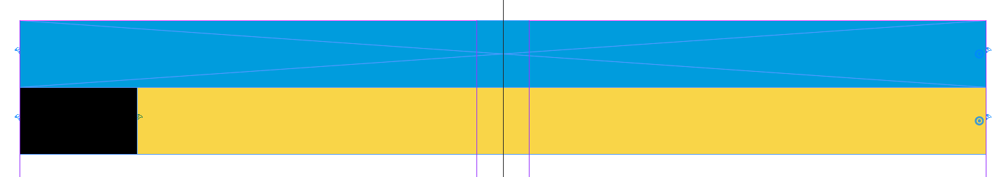
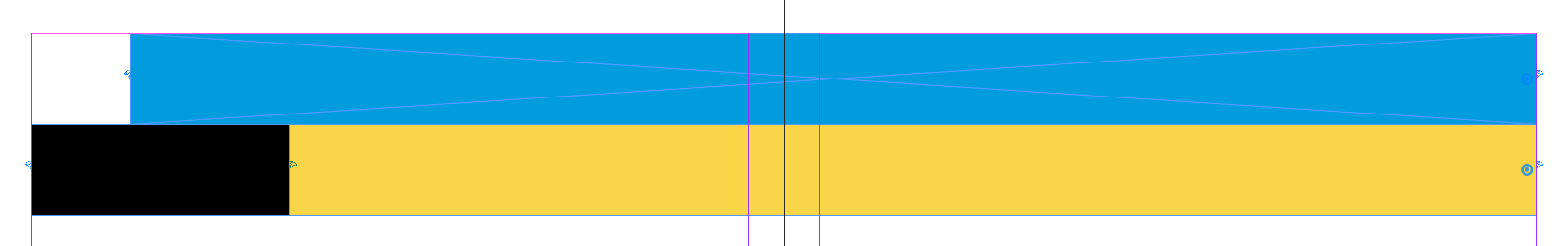
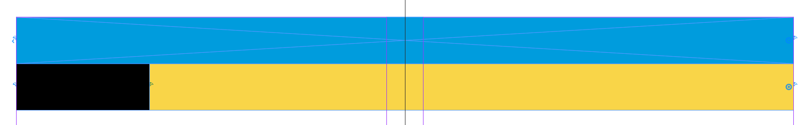
Nails on the edge of a frame determine the distance to the closest edge of the page. This distance can be fixed or relative. If two opposite frame edges are nailed, changing the page size will also change the frame size. Size changes induced this way are usually non-proportional. To achieve proportional resizing, you can nail a frame's corners.
In the two following screenshots, you can see a frame with nails on the left and right edges. The second screenshot shows the frame shrinking with the page:
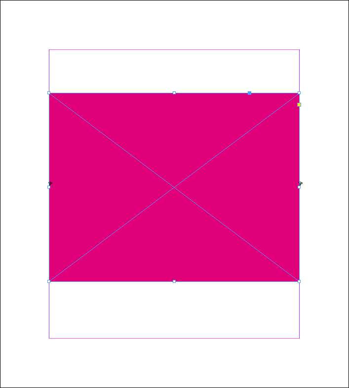 ⇒
⇒ 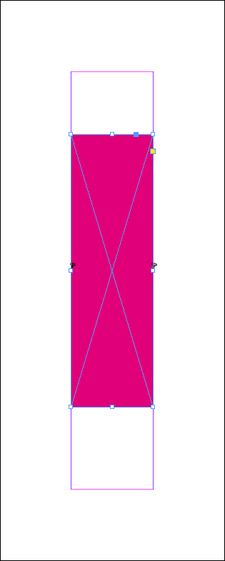
A blue nail icon represents an absolute nail, where the distance between the frame and the page edge is fixed at its exact value. Frames with nails on the top and left edges keep their positions (which isn't necessarily true of all frames when doing a normal page resize in InDesign®). Right and bottom edges are moved as follows:
posnew = posold + pagesizenew - pagesizeold
Take care when shrinking pages: If a frame is nailed on opposite edges, and the page is resized to be smaller than the frame, the frame size is set to ≤ 0. Page adaption will recognize this problem, leave the frame unchanged and mark it as adapted incorrectly.
A red nail icon represents a relative nail, which moves the nailed edge dependent on the page size. The new position is calculated as follows:
posnew = pagesizenew / pagesizeold * posold
This means that an edge at 3/4 of the page will remain there as the page is resized.
sizeold = 100
posold = 75
sizenew = 200
posnew = 200 / 100 * 75 = 150
Left-fixed frames across multiple pages of a spread need your special attention: You must specify whether the left frame edge should be oriented to the left page edge of the left page or of the right page. Default is the left edge of the parent page.
Left nails are usually oriented to the left side of the parent page. However, as you can see in the following screenshots, there are good reasons for a different decision. Here is the initial situation:
After changing the page size :
But with the default settings you will get the following result:
Yellow and black frames are correct. However, the blue frame has moved to the right along with the right page edge. This is because the blue frame "belongs" to the right page of the spread and therefore also aligns with the edges of the right side.
Frames that extend from the right page of a spread into the left page of the spread therefore need a definition of which document page their left frame edge should be oriented to.
The parent page of a frame is defined as follows:
The parent page of a frame is the document page on which the intersection of the diagonals of the bounding box of the frame falls. If the intersection of the diagonals falls exactly on a page boundary, the right page is used.
Or in other words, draw an othogonal rectangle around the however designed object. The document page that has the largest portion of this rectangle is the parent page. If two document pages have the same amount of area, the right side is used as the parent page.
Das ist nicht immer leicht zu erkennen. Rahmen über mehrere Seiten werden deshalb bei sichtbaren Nägeln und Magneten mit einem ![]() auf der Eltern-Seite markiert.
auf der Eltern-Seite markiert.
This is not always easy to see. Frames over several pages are therefore marked with a ![]() on the parent page when the nails and magnets are visible.
on the parent page when the nails and magnets are visible.
Frames that are completely on one page do not get a mark.
To bind the left side of a frame to the left page of a spread, proceed as follows:

If the left side of the blue frame is fixed now to the left page of the document, we get the desired result:
Nails in the corner of a frame proportionally scale frames depending on the change in page size. Scaling may depend on either the absolute size change, or the relative size change of the page. Pages may be resized non-proportionally. As a basis for calculating the new frame size, the smaller difference between old and new page dimensions is used.
If the page becomes smaller in one dimension, and larger in the other, the value is determined from the downsize.
A corner nail is marked with a small thermometer with low temperature (![]() ). To use the larger difference as a basis for these calculations, set the nail while holding the shift key (
). To use the larger difference as a basis for these calculations, set the nail while holding the shift key (![]() ).
).
Corner nails do not fix the frame edges! If a frame should be fixed on one or more edges, place additional Nails on Frame Edges. (This means it does not matter which corner you place a nail on.)
Corner nails use the absolute difference in size when adjusting the frame: The frame size along the axis of the smaller size change is resized by the same delta. The other axis is scaled according to the original proportions of the frame:
δw = pagewidthnew - pagewidthold
δh = pageheightnew - pageheightold
If |δw| < |δh| // > For max nails
fWnew = fWold + δw // Add width change
fHnew = fHold * fWnew / fWold // Keep proportions
else
fHneu = fHalt + δh // Add height change
fWnew = fWold * fHnew / fHold // Keep proportions
Take care when shrinking pages: If a frame smaller than the page size delta, its size would be set to be ≤ 0. Page adaption will recognize this problem, leave the frame unchanged and mark it as adapted incorrectly.
Relative corner nails use the same principle for resizing frames as normal corner nails. However, the relative page size change is applied to the original frame size, rather than the absolute delta:
δw = pagewidthnew / pagewidthold * fWold // fW : Frame Width
δh = pageheightnew - pageheightold * fHold // fH : Frame Height
If δw < δh // > For max nails
fWnew = fWold + δw // Add width change
fHnew = fHold * fWnew / fWold // Keep proportions
else
fHnew = fHold + δh // Add height change
fWnew = fWold * fHnew / fHold // Keep proportions
Magnets fix the space between frames. If a frame changes its size or position during adaption, all frames connected to it through magnets are moved to retain the spacing. If frames moved by magnets are connected to more frames, the spacing is maintained there as well.
There are four kinds of magnets:
To set a magnet, follow these steps:
 Near the middle anchor point on an edge, the mouse cursor now turns into a wave symbolthat radiates away from the frame.
 Now select the target frame. Over the middle edge points of the horizontal and vertical sides of the target frame, the mouse pointer now changes to a chain symbol and with a mouse click the two frames are connected.
 Hold the Alt key while hovering over magnet end points, and the mouse cursor will turn into a scissors icon. Click to remove the magnet.
The current magnet spacing is stored with the involved frames and updated whenever the frame geometry is changed outside of page adaption.
Please also note the following:
Absolute magnet spaces are restored to their exact previous size after page adaption.
Relative magnet spaces are scaled relative to the page size after page adaption:
distnew = distold * pagesizenew / pagesizeold
Alternative Magnets are used when the position of a frame depends on the size of multiple frames. They can point to edges that already have a normal magnet. To place alternative magnets, hold the Alt key while selecting the target frame. Alternative magnets are represented by a dashed line connecting the frames. You can place up to 8 alternatives.
Alternative magnets function as follows:
The yellow frames should be fitted to their content during page adaptation.
However, the largest frame should always have the same distance of 15 mm to the largest of the three yellow frames.
You need one magnet each between the yellow and the green frame (first picture).
In the second picture you can see the result of the adaptation: the first yellow frame becomes the highest and
the alternative magnets move the green frame so that it is 15mm below this frame.
⇒
Magnetic pixels drag another frame behind them when resized: The frame always remains at the same image point, no matter how the image frame or image are moved or scaled. Frames and images may be rotated, but the image rotation must not change during adaptation. Several magnetic pixels can be defined in one image.
Magnetic image points can only be set on image frames. Image points are not magnetic until you have set an image magnet in both dimensions.
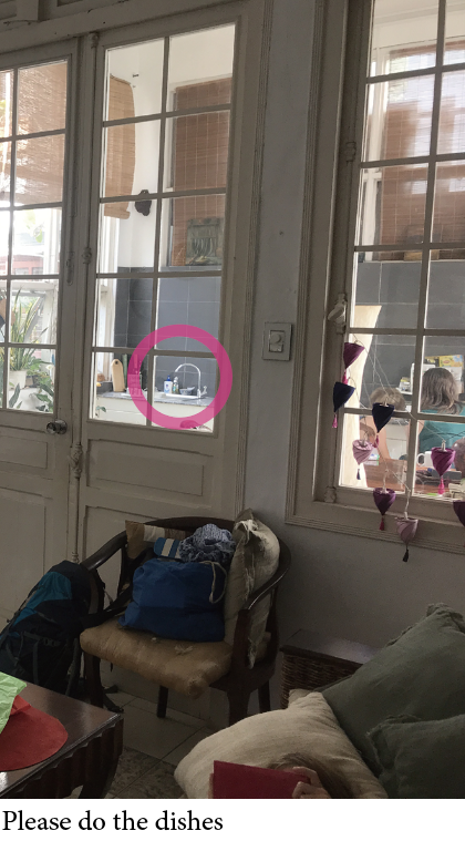
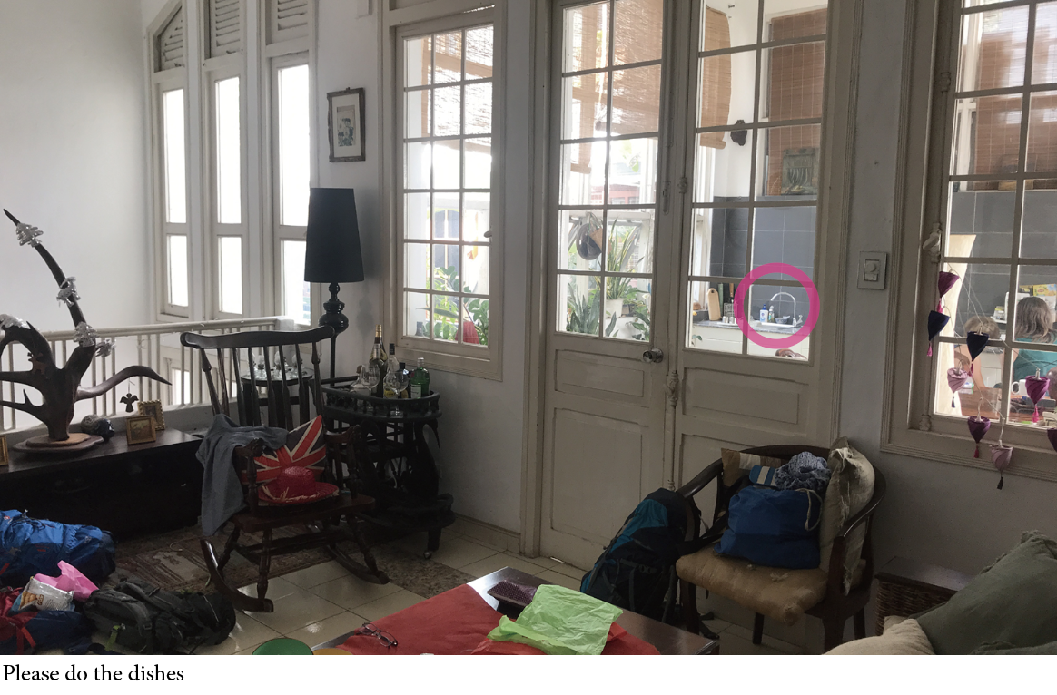
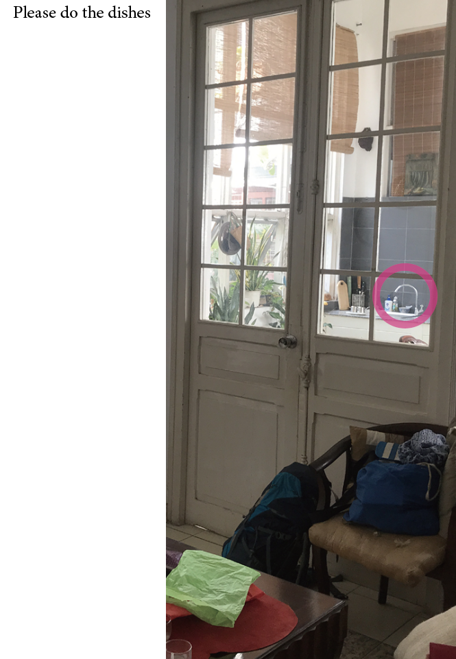
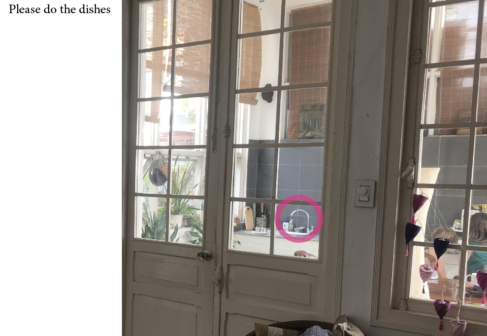
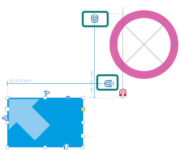
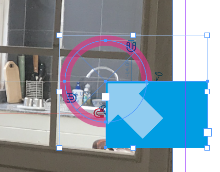
The screenshots show two different and differently sized sections of a kitchen. The sink is highlighted with a red red circle. The circle is not part of the image. The image frame is adjusted to the document size with nails on each side and the image content is adjusted to the new frame size. You can find the sample document here.
 ⇒
⇒
Here's how to do it:
Create a frame that will follow the pixel. In the screenshot this is the blue frame.
Place this frame and the red circle next to the image in such a way that
both can be easily selected.

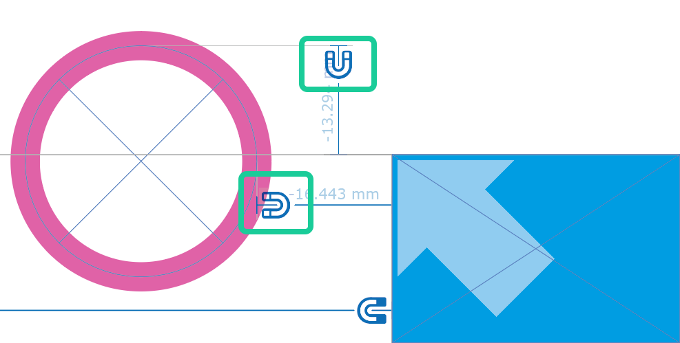
![]() Select the normal magnet tool.
Select the normal magnet tool.
Click the left (or right) side of the image.
With the Shift key held down, click the same side of the blue frame.
Repeat the same for the top (or bottom) edges.
A thick arrow will now appear in the corner of the two edges to mark
which corner of the frame is magnetic.

With this you would (actually) be finished. But surely you have noticed that only the corner points of the movable frame (here the blue frame) can be magnetized. In the example, however, the center of a frame (here the red circle) is to be placed. And since resizing will also change the scaling of the image, unfortunately it won't help to center the magnetic frame on the desired point in the image.
The solution is a very simple trick: Place the red ring with its center
exactly on the upper left corner of the blue frame.
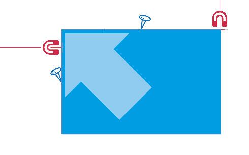
So that the ring will follow the blue frame, place two normal magnets
from the blue frame to the red ring.
In the screenshot the two magnets are are marked in green and the red ring is not yet
exactly placed for better handling:
Finally, place both frames to the desired point in the image: t
the blue frame with the corner of the arrow and the red one in the center.
Since the blue frame is only a helping contruction here, you can
(for this example) make it invisible now.
To do this, use the Layers panel, 0% opacity or simply place the frame behind the image.

The image pixel magnet is the counterpart to the Magnetic Pixel. Here, the image does not drag a frame behind it, but a frame drags the image: The Image Pixel Magnet places the image so that a specified image point is always at the same position on the page.
A prerequisite for the pixel magnet is a reference frame. The frame may be invisible.
A pixel (here the water tap of the sink) shall always be shown in the same distance to the upper left corner of the document and be highlighted with a red circle - which does not belong to the image. The image itself is always adjusted to the document size with four side nails and the contained image is scaled accordingly. You can find the sample document here. Here are two screenshots:
 ⇒
⇒
Here's how to do it:
The first thing you need do is create a 'helper' frame.
This frame will later pull the image to the right place.
Place this frame and the red circle next to the image so that both can be
selected easily.

![]() So that the blue frame always has the same distance to the upper left corner of the document,
you should set nails at the top and at the left.
So that the blue frame always has the same distance to the upper left corner of the document,
you should set nails at the top and at the left.
![]() Choose the tool Red Magnet.
Choose the tool Red Magnet.
Click the left side of the image frame.
Shift-click the left side of the blue frame.
Repeat this with the upper edges.
In the frame, a thick arrow now points to the upper left corner and the red magnetic marks
point to the left and upper edge of the image content:
With this you would (actually) be done. But surely you have noticed that only the upper left corner of the blue frame can be selected as to be the fix point. In the example, however, the center of a frame (here the red circle) is to be placed. And since resizing will also change the scaling of the image, it unfortunately doesn't help to simply center the subframe at the desired point in the image.
The solution is a very simple trick: Place the red ring with its center
center exactly on the upper left corner of the blue frame.
So that the ring will follow the blue frame, place two normal magnets
from the blue frame to the red ring. In the screenshot the two magnets are
marked in green and the red ring is not yet exactly placed for better handling:
Now the fine-tuning: Place the blue and red frames at the desired image position.
Make sure that the center of the red ring is on the upper left corner of the blue frame.
After that you can make the blue frame invisible (Layers panel, 0% Transparency or simply move it behind the image).
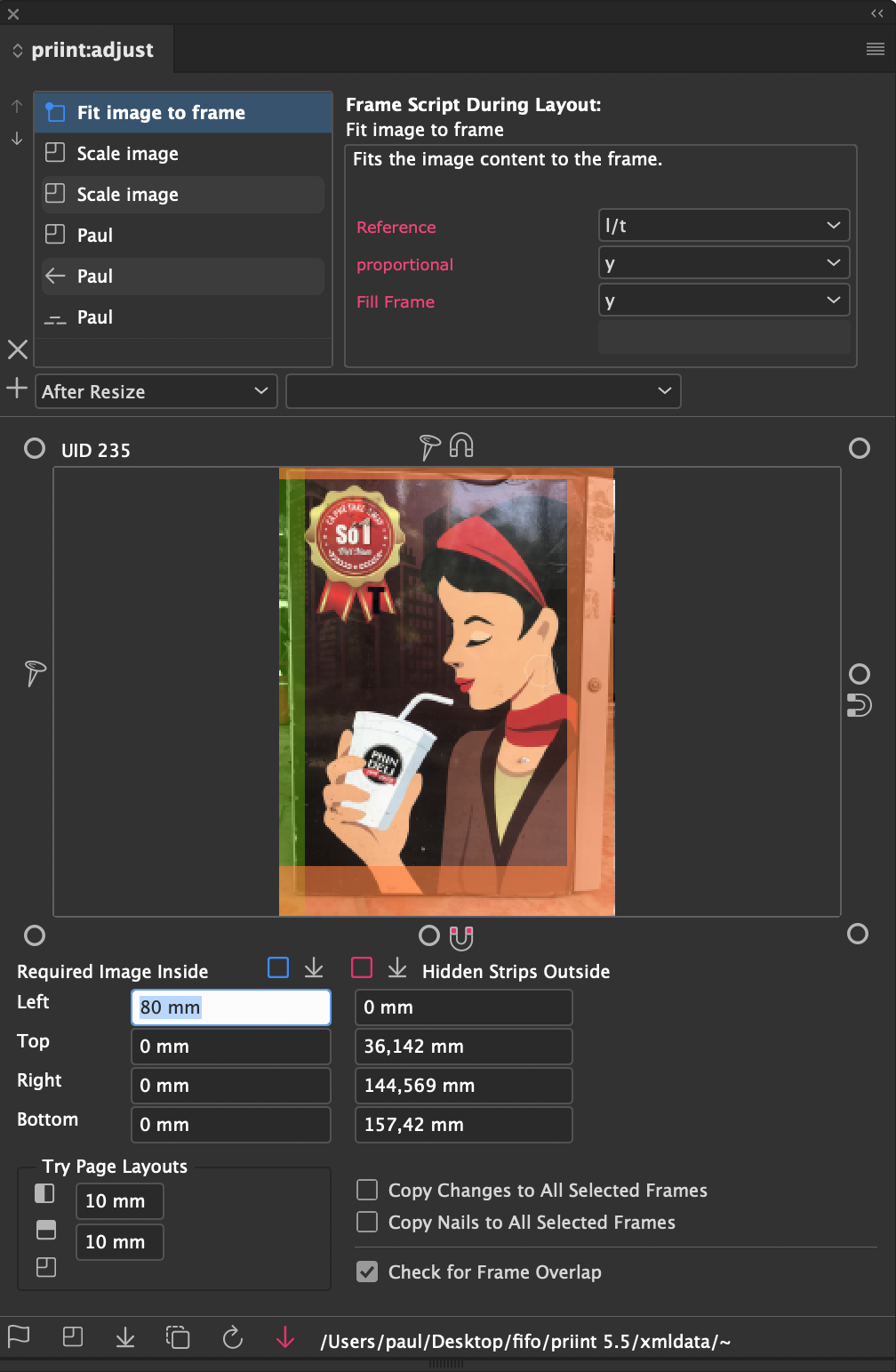
The purpose of page adaption is to layout frames on a page according to the nails and magnets in a geometrically correct fashion. Frames may move or change in size during this process. This may in turn require adjusting frame contents, which can be controlled by assigning rules to the frames. All available content rules are shown in the corresponding popup menu in the priin:adjust panel.

The rules for adjusting frame contents are not delivered with priint:adjust. You can obtain preconfigured solutions from WERK II upon request. Feel free to contact our support about this. You can find pointers on how to build your own rules here.
Scripts may run in one of the following contexts:
Any number of rules can be assigned to any given frame. To do so, select the desired rule and the context it should be applied in, and click the + to the left of the two popup menues. During adaption, the rules are automatically executed in the specified situations. The order of execution corresponds to the order in the list. You can change the order using the arrows to the left of the list.
When a rule is added to a frame, its ID and the full source code are stored in the document frame. This allows the rule to be executed without requiring the original data pool. Adaptions can even be executed properly, if the original source of configuration is no longer available (the priint:adjust plugins still have to be installed, of course).
When rules are changed in the configuration, this has no effect on the scripts stored in a frame. You can use the Update Button ![]() in the priint:adjust panel to reload the rules from the configuration. All rules stored in the document that are also defined in the configuration are overwritten with their new content. Rules are therefore associated with an ID. Manual changes to the rules in the document are lost in this process.
in the priint:adjust panel to reload the rules from the configuration. All rules stored in the document that are also defined in the configuration are overwritten with their new content. Rules are therefore associated with an ID. Manual changes to the rules in the document are lost in this process.
Rules can be deactivated and activated. By default, rules are active upon assignment. For testing purposes, it can be helpful to temporarily disable application of certain rules. Click the status field in front of the script name. The entry is then disabled and displayed in gray:
If you have a Comet Partner License, you can edit the scripts implementing the rules. Simply double click the rule in the list. In the appearing window, you can edit the script. By pressing the "Save" Button in the editor, your changes will be written to the document. The change only affects the one script, and only within this document. This does not affect the scripts in your configuration data. You can revert your changes using Undo.
Adapter Rules are stored as cScript code in the file or database table actions with the TypeID 35. All actions of this type are automatically loaded into the corresponding popup menu in the priint:adjust panel. To deactivate an entry in the popup menu, assign the classid -1 to it in the actions definition.
From these scripts you have access to all script functions, giving you the full power of cScript. In addition to gFrame, gDocument, etc., a number of global variables is defined for these scripts. The following table lists and describes all of them. To make these available, use this include line:
#include "internal/types.h"
| Name | Type | Description |
| gScriptType | int | What context does the script run in?
kActionBefore Make sure to perform these checks at the beginning of the script. |
| gPageWidthOrg gPageHeightOrg |
float | Original size of the frame gFrame in points. |
| gPageWidthNew gPageHeightNew |
float | New size of the frame gFrame in points. |
| gResizeX gResizeY |
float | Resize factor of the current size change (1.0 being equivalent to 100%). This value is only defined in the kActionAfterResize context. Otherwise, it defaults to 0.0. |
| gPage | int | Current page number (1-based) |
| gOrgFrame | ItemRef | This variable is only defined for the purpose of backwards compatibility. It is always 0. To find the size of the original frame, use gOrgFrameLeft and the related variables. |
| gOrgFrameLeft | float | Coordinates (in points) of the frame gFrame before the adaption of the document |
| gOrgFrameTop | ||
| gOrgFrameRight | ||
| gOrgFrameBottom | ||
| gLastFrameLeft | float | Coordinates (in points) of the frame gFrame before the adaption of the frame (which lead to the execution of the script). |
| gLastFrameTop | ||
| gLastFrameRight | ||
| gLastFrameBottom | ||
| gOrgImageLeft | float | Coordinates (in points) of the image within the frame, before the adaption of the document. There are no corresponding gLast~ variables, since the adaption leaves image frames untouched. |
| gOrgImageTop | ||
| gOrgImageRight | ||
| gOrgImageBottom | ||
| gLastResizeX | float | Change in frame size relative to the last step of the adaption (1.0 being equivalent to 100%). |
| gLastResizeY | ||
| gOrgResizeX | Change in frame size relative to the original before the adaption (1.0 being equivalent to 100%). | |
| gOrgResizeY | ||
| gParam1 gParam2 gParam3 gParam4 |
char* |
Each script can use up to four parameters which can be specified in the panel. The values are stored in the frame, one set for each rule. You can find more about how to configure the labels below. Script variables each contain the values specified here: gParam1 contains the value of the first field as a string, and so on. The ~Int variables contain the same value converted to an integer (where possible), and the ~Float variables contain the corresponding floating point value. |
| gParamInt1 gParamInt2 gParamInt3 gParamInt4 |
int | |
| gParamFloat1 gParamFloat2 gParamFloat3 gParamFloat4 |
float |
The following example shows a script that sets the font size of a text frame according to the size change of the adaption. Parameters 1 and 2 can be used to set the lower and upper bounds of for the font size, respectively. If parameter 3 contains the word "integer", the font size is guaranteed to be an integer, not a rational number like 14.1.
#include "internal/types.h"

int main ()
{
    float   resx  = gResizeX;
    float   sz    = 0.0;
    int     isz   = 0;

    if (gScriptType != kActionAfterResize || gResizeX == 1.0) return 0;

    sz = textmodel::get_fontsize (gFrame, 0);
    if (sz <= 0.0) return 0; // Error

    // Should the font size be an integer?
    // Check if parameter 3 contains the word "integer"
    if (strcmp (gParam3, "integer") == 0)
    {
        isz		= toint (sz * resx);
        resx	= tofloat (isz) / sz;
    }

    // Parameters 1 and 2 contain the minimum and maximum font size
    // NOTE : The values could be empty!
    if (gParamFloat1 > 0.0 && (sz * resx) < gParamFloat1) resx = gParamFloat1 / sz;
    if (gParamFloat2 > 0.0 && (sz * resx) > gParamFloat2) resx = gParamFloat2 / sz;

    // Scale to new font size
    wlog ("", "# Scaling to new font size %f\n", sz * resx);
    textmodel::scale_font (gFrame, 0, -1, resx);

    return 0;
}
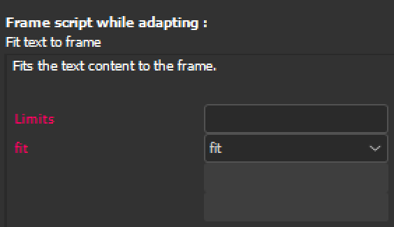
In the screenshot below you can see the rule Fit text to frame and its parameters.
Red : The red labels Limits and Adjust indicate that the parameters belong to a rule that is already assigned to a frame and changes to the parameter values will be carried over into the document.
Black : If the parameter labels are black, only the rule definition and the help texts from the current configuration are shown.
The names of the four parameters are defined separated by ## in the outputdocumentation field of actions. If a name is empty (####) or missing, no parameter name is shown. An additional # in front of the parameter name deactivates the input field. If possible, parameter names are translated into the current InDesign® language.
Here is a very simple example that deactivates the last two parameters.
<outputdocumentation>Value 1##Value 1######</outputdocumentation>
Some parameters require a fixed list of input values. These values can be displayed as pop-up menus. The list of values is added to the respective parameter name separated by a line separator (\n, \n\r, \r, , ). The entries in the list are also separated by line separators. A ! at the beginning of an entry marks the entry as the default entry. A minus (-) creates a separator in the popup. The parameter name and values are trimmed (all whitespaces before and after are removed).
The text selected in the pop-up is passed on as the parameter value. Values in pop-up menus are therefore not translated for obvious reasons.
Here is the definition for the rule from the screenshot above:
<outputdocumentation>
    limits
    ##fit
        grow
        shrink
        !fit
    ###
    ###</outputdocumentation>
In the inputdocumentation field of actions, (optional) help texts can be defined to describe the function and its parameters.
For historical reasons, the description must begin with the prefix unused##0##. This is followed by the help texts for the function and its four parameters, each separated by ##. Missing information is ignored. If possible, help texts are translated into the current InDesign® language.
Here is an example.
<inputdocumentation>unused##0##fits the text content to the frame.
    ##Text size limits, e.g. 10-40
    ##Supported methods
</inputdocumentation>
Please note: To ensure that adaptation rules are also available without the current data configuration, script texts, parameter names and help texts are inserted directly into the document. Parameter names and help texts are inserted in the current translation and are also displayed in this language in other language versions of InDesign®.
With the  - button in the panel you can create a multi-adaption of the current file. This requires a control file, containing information about target direcories, file names and the desired target formats. The control file is expected to contain valid XML of the following form:
<?xml version="1.0" encoding="utf-8"?>
<adaptions
	basename = ""
	folder = "$DESKTOP/adapt/ok"
	errfolder = "$DESKTOP/adapt/err">
	<adaption>
		<format>A5</format>
		<width></width>
		<height></height>
		<name></name>
   </adaption>
   <adaption>
		<format>A4</format>
		<width></width>
		<height></height>
		<name></name>
	</adaption>
	<adaption>
		<format>A3</format>
		<width></width>
		<height></height>
		<name></name>
	</adaption>
</adaptions>
The filenames are generated from basename (unless it is empty), the name of the current document and the page size. The page size of the target document can be specified as a format name or in points. If a format name is provided, the width and height fields are ignored. The following table shows the supported format names and the associated page size:
| Name | Width x Height in Points |
| US-Letter | 612.0 x 792.0 |
| US-Long | 612.0 x 1008.0 |
| US-Letter Half | 396.0 x 612.0 |
| US-Long Half | 504.0 x 612.0 |
| Tabloid | 792.0 x 1224.0 |
| A3 | 841.89 x 1190.551 |
| A4 | 595.276 x 841.89 |
| A5 | 419.528 x 595.276 |
| B5 | 498.898 x 708.661 |
| CD | 340.0 x 342.0 |
cScript offers a number of functions to support page adaption, nails and magnets:
Here is one example in JavaScript:
var originalDoc = "/Users/paul/Desktop/aaa.indd";
var newWidth = 595.276 * 1.5;
var newHeight = 841.89 * 1.2;
var doc = app.open(File(originalDoc));
doc.adapt (newWidth, newHeight);
doc.close (SaveOptions.YES);
If an error occurs during page adaption, it is usually terminated. Further description of the error can then be found in the log file. You can activate the log file using the menu Plug-Ins -> Write log file... . The following logical errors are recognized by the adaption and do not result in aborted adaption. The errornous frames are marked in the document.
Error markings are automatically removed befor the next adaption, and can manually be removed using Flyout Menu Reset Error Marks of the priint:adjust panel. To display error marks, activate the context the entry Nails and Magnets -> Show Errors in the document's context menu.
Size errors occur when a frame is resized to a size < 0. In such cases, the frame remains unchanged, and are marked with a bright triangle in the lower right half of the frame:
Changes to frame overlap are the most common adaption error. Both types of change are detected here: whether new overlap occured or existing overlap was lost. Both frames involved in an overlap error are highlighted by a 2x2 grid:
 ⇒
⇒ 
The checks for overlap errors for the current document can be disabled in the priint:adjust panel. Warning: This setting is stored with each document, not your plugin configuration.
For rotated frames, overlap is checked against their BoundingBox, which will occasionally produce false positives. This problem will be fixed in an upcoming version of the program.
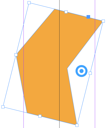
Size changes to rotated frames can lead to non-orthogonal distortions of the frame.
You can recreate this effect without nails or magnets, only using standard InDesign® tools:
 ⇒
⇒ 
The problem here is that, in increasing the width of the group, its height would have to be adjusted to retain the original proportions. Since you only used an anchor point on a side, the height remained the same, with no additional degrees of freedom. Thus InDesign® distorts the frame for lack of a better solution.
Hint : To restore such a frame to be a recheck frame, use the InDesign® menu Object -> Convert Shape -> Rectangle.
The same problem occurs during page adaption when a rotated frame is resized by nails or magnets along both axes. In all other cases, we solved the problem algebraically. This is not possible in this case, so the frame is marked with a white circle:

This error occurs only when the Update Button  in the panel is used. The error is displayed as text above the frame.